V1 Plunger manual click HERE
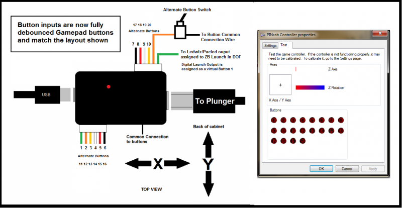
Button wiring info for the gamepad only version is:
Button wiring info for the keyboard version is:
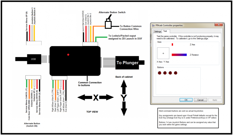
The diagrams are hard to read so here is the pinout chart for the keyboard firmware:
Lower connector (as pictured above) regular functions:
Right magnasave (R_ctrl), Start (1), Left Flipper (L_Shift), Right Flipper (R_Shift), Left magnasave (L_CTRL), End (e)
Upper connector:
Launch Ball (Enter), Coin (5), Joystick button 1, joystick button 2, Alt_button Switch trigger, ZB Launch feature trigger
Lower Connector alt functions (when alt-button wired is grounded)
Service menu CANCEL (7), Coindoor OPEN (END), Volume DOWN (+), Volume UP (-), Service Menu ENTER ( 0 ), Service menu DOWN ( 8 )
Upper connector alt functions:
Service menu UP (9), N/A, Joystick button 3, Joystick button 4
Volume buttons are reversed in diagram and controller USB cable now comes out beside the common wire.