When mixing 24V and 12V contactors/solenoids on the contactor bank you will need to install diodes on the 12v solenoids at the solenoid and make the following modification to the board.....
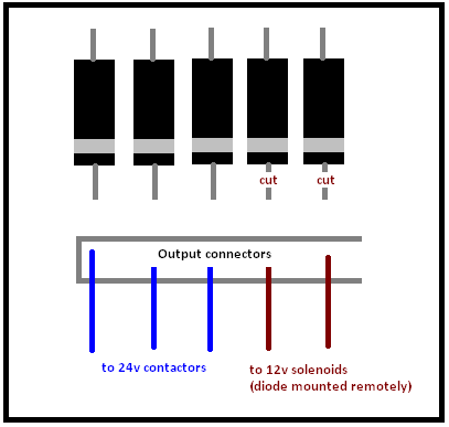
This will avoid mysterious locking on of the outputs used for 12v solenoids.
When 2 diodes are placed in parallel across different voltages a path is created between the 2 voltages that allows current to flow when the output is off. When the solenoid that is connected is 12v and the contactor voltage rail is 24v, the 12v device connected to the rail has the power it needs to operate when the output is in the off state.